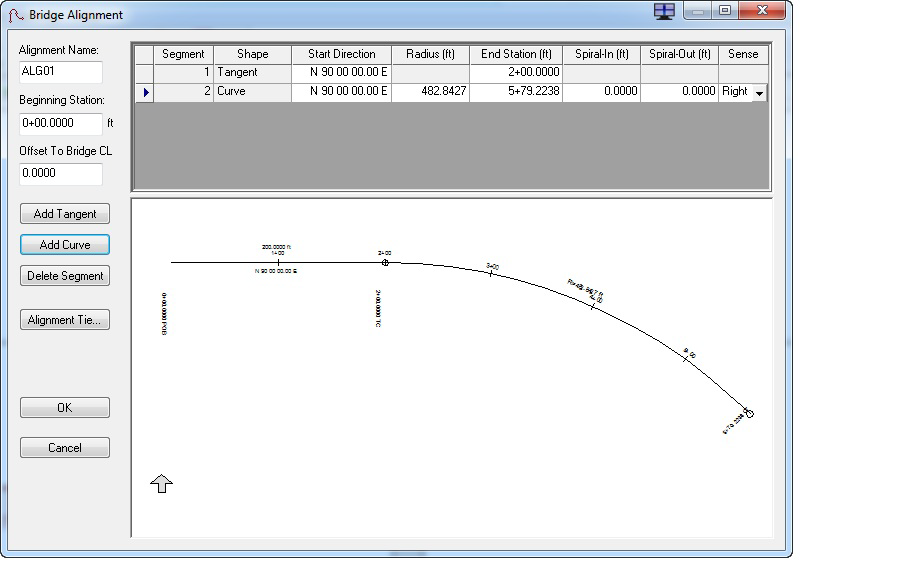
Bridge Alignment Dialog Box
The Bridge Alignment dialog box allows you to define a bridge's alignment by creating, modifying, or deleting alignment tangents and/or curve segments. To open this dialog box, click the Alignment button on the Geometry tab.
CIP RC/PT Girder allows the user to input bridge geometry directly from the plans. The program uses the actual layout geometrics to assist the user in defining the analysis model. The designer must determine appropriate span lengths for the analysis. When bridges are on roadway curves and/or include skewed supports, the distance between supports can vary, thus making the analysis model difficult to define. CIP RC/PT Girder assists the designer by computing the distance between supports along the centerline of the bridge and, if desired, along the centerline of each girder. By default,CIP RC/PT Girder creates a straight alignment along a N 90 E bearing. When a segment is created, deleted, or modified, all ahead-station segments in the bridge layout line automatically adjust themselves, thus maintaining individual segment lengths and angles relative to their back-station neighbor.
Adding Tangents
This function adds a straight segment to the bridge alignment after the selected segment. The new segment is tangent to and equal in length to the preceding alignment segment.
Adding Curves
This function adds a curved segment to the bridge alignment after the selected segment. The new segment is tangent and equal in length to the preceding alignment segment. When creating a curve, note that spirals can only be used to connect tangent segments with a circular arc and vice-versa, i.e., one end of the spiral has an infinite radius (tangent) and the other uses the radius of the circular arc.
Deleting Segments
This function deletes a segment from the bridge layout line and adjusts the starting direction of the following segment to create the effect of having progressively shortened the length of the deleted segment to zero.
Perform the following steps to delete a segment from the bridge alignment:
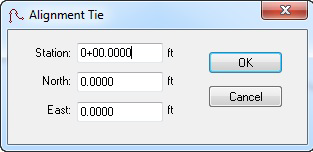
Creating Alignment Ties
CIP RC/PT Girder can export/save plan view data to CAD formats. Users can choose to tie exported/saved data to the state plane coordinates by identifying a location along the alignment and specifying an appropriate coordinate value by clicking the Alignment Tie button to open the Alignment Tie dialog box.
Grid Definitions

| Setting | Description |
|---|---|
| Beginning Station | Define the beginning station of the bridge alignment. |
| Offset to Bridge CL | Define the lateral offset from the alignment to the centerline of the bridge. |
| Segment | This noneditable field displays the segment number of the alignment. |
| Shape | This noneditable field lists whether the segment is a tangent or a curve. |
| Start Direction | Enter the starting direction of the segment. By default, the starting direction is equal to the direction of the end of the preceding segment |
| End Station | Enter the ending direction of the segment. |
| Radius | Enter the radius for a curve segment. |
| Spiral-In | Enter the spiral-in for a curve segment. |
| Spiral-Out | Enter the spiral-out length for a curve segment. |
| Sense | Select the curve sense (left or right) from the drop-down list. |
Technical Discussion
The user can make use of CIP RC/PT Girder 's alignment to describe structures on complex layouts including offsets from the alignment to the centerline of the bridge. The user can then enter geometric data exactly as defined on the construction drawings and allow CIP RC/PT Girder to determine exact member distances and connection locations. By default, the alignment is defined as a tangent bearing N 90 E. The primary use of the alignment is to describe structures on curves or having skewed substructures, which will be analyzed using the Optional Girder Analysis option.